

Inline Skating
 MiniDisc Hacks
PC Utilities
Free Games
MiniDisc Hacks
PC Utilities
Free Games
Liikenne
Palvelut
Vinkit
Fixing Canon PowerShot S200 Lens Error
How to replace the lens or diaphragm assembly
 Canon PowerShot S200 (code: PC2033) camera and similar models (like PowerShot S100 or S110) are known for "Lens error". If the lens error is not caused by mechanical damage (dropping the camera, sand in the lens barrel), it is likely that the reason is cracked diaphragm (aperture iris) flex cable. The latter may happen even if the camera is handled 100 % carefully during its life.
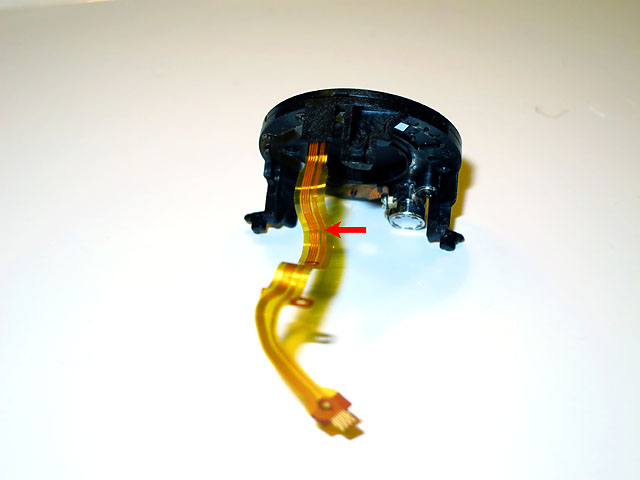
Folded flex cables in the storage position and a crack on the diaphragm flex cable
Same failure mode is known on Canon's professional lenses but because S200 is pretty thin when off, the flex cable is stressed even more: The diaphragm assembly is located close to the outer lens and therefore it needs to move a lot with the zoom. Such movement requires a pretty long flex cable, which needs, on the other hand, to be folded pretty heavily when the lens is in the storage position. Repeated folding stresses the cable and, eventually, the cable will get a sharp fold cracking the conductors inside.
To fix the problem you have three different options (in order of decreasing spare part cost):
- Replace whole lens barrel assembly, including the CCD sensor. Pretty easy task, but the replacement barrel is most probably a used one and may have the same failure mode soon (happened to me: the replacement lens worked only three weeks!)
- Replace the diaphragm assembly with its flex cable. This needs disassembly/reassembly of the lens barrel in addition to above but no soldering is needed.
- Replace only the diaphragm flex cable. I have never tried this because it needs good soldering skills and stable hands in addition to all of above.
I do not have any detailed pictures about the repair procedure but below I have listed the steps needed during repair; so you do not need to guess everything from scratch. For step-by-step pictures, see this guide (it is not for the exactly same model but anyway helps in understanding the steps below).
Note that a dust-free ESD safe working environment is required to avoid further damage and dirt in side the lens. Do not scratch your head — hair protection is recommended!
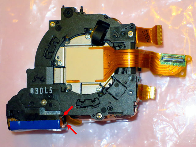
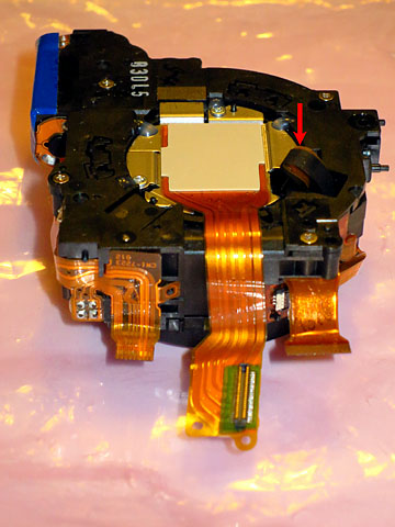
Canon PowerShot S200 lens assembly and the zoom motor contacts
Lens removal
WARNING: The flash unit may contain dangerous voltages. Be careful not to touch its electronics by accident with hand or a tool!- Of course, remove the battery and memory card first.
- Remove front and back covers by unscrewing six screws visible outside (white screw heads).
- Unplug the selection ring cable from the main board to remove the front cover completely.
- Lift off the dust gasket around the lens barrel. Note its orientation; the faces are different.
- Remove the heat sink sheet located on the top of the main board (one screw).
- Unplug four flex cables: top controls/microphone/Wi-Fi cable, top lens control cable, bottom lens control cable and the CCD cable in the middle (just lift it carefully until it snaps out)
- Unscrew a screw close to the camera ports and another just above the lens to release the top cover (no need to detach the microphones from the top cover).
- Unscrew one screw holding the Wi-Fi module in place so that it can be lifted away with the top cover (no need to unplug the Wi-Fi module from its cable).
- Unplug the flash assembly flex cable located on the top of the camera (snap it out by lifting like the CCD cable)
- Unscrew the screw at the top-right corner of the display to release the steel bracket locking the display in place.
- Turn the display carefully almost 90 degrees to access the screwheads beneath of it.
- Remove the flash assembly by unscrewing two screws behind the left part of display.
- Carefully detach the flash unit connector from the black plastic support (it is attached there with sticky glue) to expose a screw head.
- Unscrew the screw to remove the plastic support.
- Remove three screws (the smallest ones) behind the display to remove the lens assembly. (No need to unscrew the slightly bigger screw close to the tripod thread.)
- Remove the lens barrel from the camera body (it is slightly behind the tripod block but it is possible to guide it out from there).
Carefully follow the instructions in reverse order to reassemble the camera. Keep track of the screws: not all of them are similar. In addition, ensure that each component is perfectly in place before tightening any screws.
To make the removed lens more easy to handle and disassemble, connect a 3-volt power supply (e.g. two alkaline batteries in series) shortly to the two big solder contacts of the zoom motor (the motor horizontally below the barrel). Try opposite polarity if the zoom does not retract to the storage position immediately.
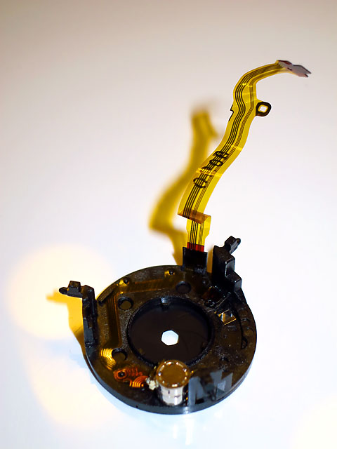
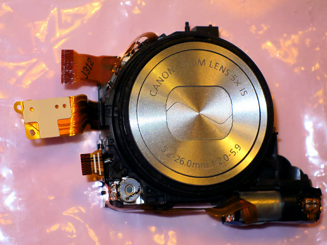
Aperture diaphragm assy
Lens disassembly (for diaphragm removal)
In order to clean any dust practicles from the inside of the lens barrel, prepare yourself with air duster spray or something similar. However, use air blower judiciously: too extensive use of dry flowing air may result in electrostatic charges and damage electronic parts.Important: After opening the lens assembly, carefully keep the lens barrel components in place so that they are not accidentally getting out and rotated relative to each other! It is a pretty difficult 3D puzzle to solve if they are moved.
- Unplug the two flex cables (diaphragm and image stabilizer cables; latter has a black protective tape on it) on the outer side of the lens assembly.
- Unscrew four small screws from the back to remove the CCD and motors from the lens barrel. Do not touch the screws keeping the CCD itself in place.
- While holding the lens barrel pieces in place (the lens cover spring constantly tries to push the innermost one slightly out), turn the ring gear of the zoom with a screwdriver until the zoom is half-way out and the slot where the flex cables go through the barrel is exposed.
- Pull the flex cables from the slot into the barrel. Now you can inspect the cables for any cracks – they are located at the tightest bends of them.
- Rotate the zoom gear back to the storage position (the end of the gear teeth). It just stops there if you remember to keep all parts pushed together all the time.
- Let the innermost part of the barrel to lift out a bit and rotate it slightly (only a few degrees) counter-clockwise so that the three notches on it are aligned with the three image stabilizer (IS) unit guides. This would need some patience because it is somewhat difficult to find the correct position of pieces to allow the rotation.
- Lift the IS assembly out from the barrel.
- Rotate the innermost part slightly more to align the notches with the diaphragm assembly guides.
- Lift the diaphragm assembly out from the barrel.
I used two layers of thin transparent office tape; no idea if it will work in the long run or not. After completing lens reassembly, it looked that the cable is a little bit less folded at the critical point. However, there is really no extra space in the camera for the cable, so it might be possible that the cable is folded anyway in the old way when the camera is completely reassembled.
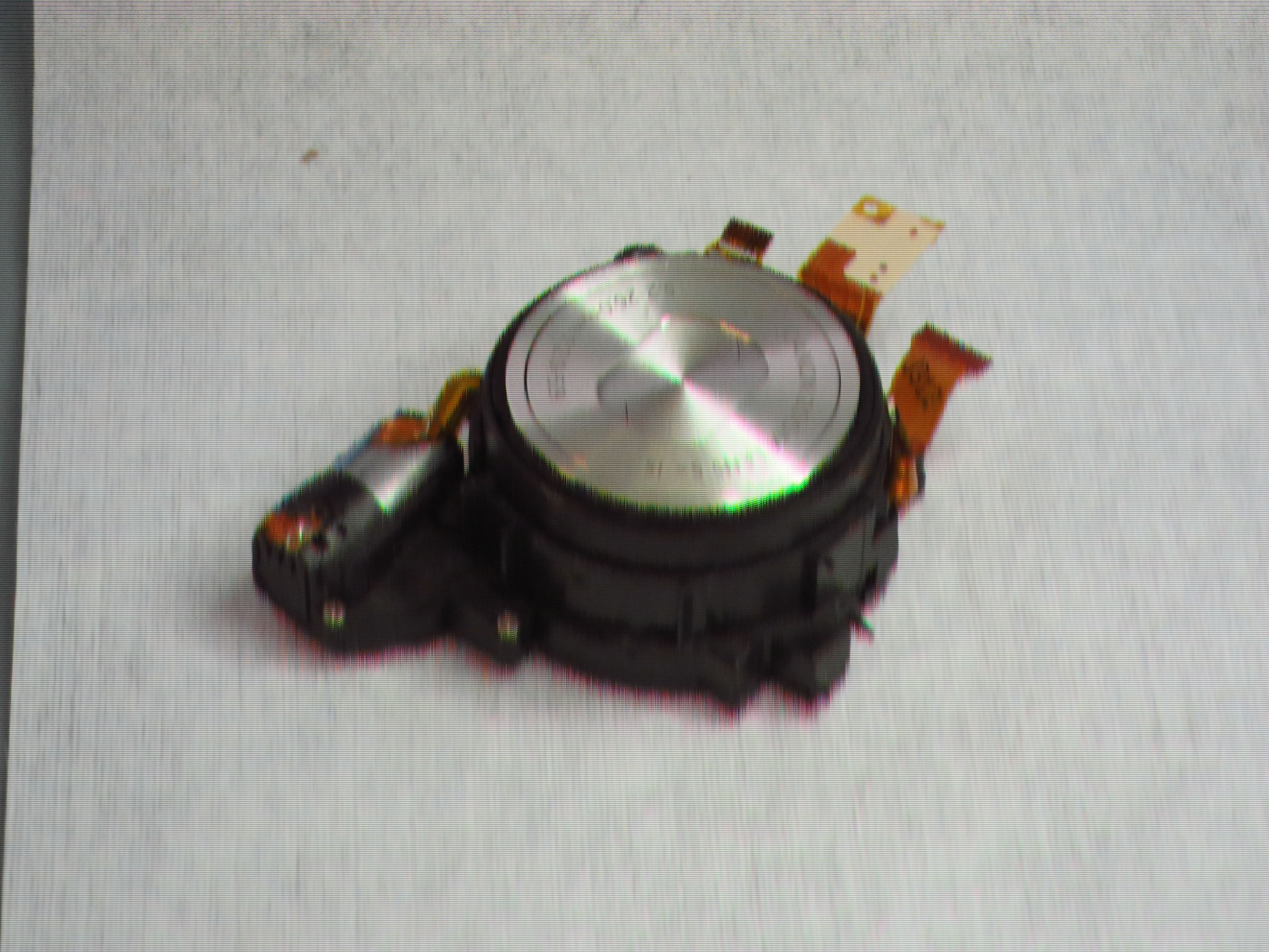
Distorted image (click to view original)
After each step, carefully check if there are any plastic claws or pins for flex cables where the cables should be placed/attached. Most probably you cannot put the cables there after the next step anymore.
CCD failure
During my first attempt of diaphragm replacement, the lens error was resolved but the pictures were severely distorted (see example on the right) and purplish (not visible in the example).I expect that the CCD sensor was damaged either because of my extensive use of air blower spray to clean dust away from the part containing the CCD or just because my original brutal disassembly attempts in order to guess the faulty part.
Luckily I had a working CCD on another lens unit (which I initially used to fix the lens error for the first three weeks), so just swapping the back part of the lens assembly solved the problem. But anyway, I recommend extreme carefulness with the back part of the lens assembly: put it on a clean and antistatic surface face down away from everything so that it does not get any dust and does not need to be cleaned. You have been warned.